.png)
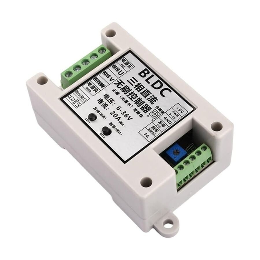


ZS-X14 DC 6-36V 20A BLDC 3 Phase Brushless Motor Driver
ZS-X14 DC 6-36V 20A BLDC 3 Phase Brushless Motor Driver
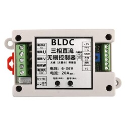
ZS-X14 DC 6-36V 20A BLDC 3 Phase Brushless Motor Driver is designed for BLDC brushless DC motors.tors. The controller allows you to adjust the rotation speed and change the direction of rotation of the motor. there is a wide supply voltage December from 6 to 36V DC, the maximum output power of the module is 400W.
Features
- Model: ZS-X14
- Operating voltage: 6-30V (limit 36V)
- Drive current: 18A rated with 25A heat dissipation process
- Power: rated 250W-300W, 400W (please leave margin for usin for use)
- Overcurrent ercurrent protection: Yes
- Locked rotor protection: Yes (after the locked rotor, the current runs aut runs automatically and in isolation)
- Over-temperature protection: Yes (on: Yes (over-temperature power is reduced by half)
- Maximum speed: 224000 RPM (2-pole motor), 74000 RPM (6-pole motor), 40000 RPM (12-pole motor), 35000 RPM (14-pole motor)
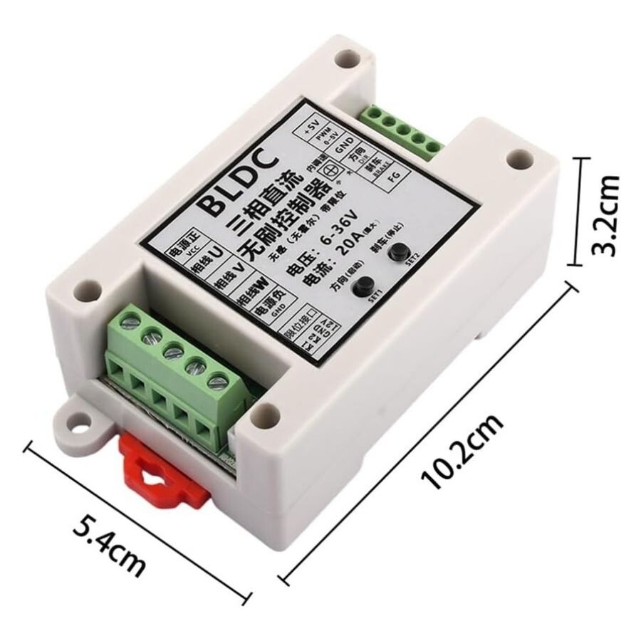
- Size: 10.2x5.4x3.2cm
6 mode operation instructions withions with limit fu limit function
1. Standard mode stepless speed regulation: Press and release SET1 to turn forward or backward, press SET2 to brake and stop at the limit position
2. Automatic mode stepless speed regulation: Press the SET1 key to start SET2, stop when you encounter a limit, and use the limit switch to achieve automatic back and forth repeating operation
3. Deceleration mode, stepless speed regulation, press SET1 key, forward turn, stop stop, press SET2 key, reverse turn, stop stop, limit stop
4. The only round-trip mode is stepless speed regulation. Press the SET1 key to start and stop SET2. When a border stop is encountered, automatic round-trip operation is achieved via the border switch
5. Single trigger mode stepless speed regulation. Press the SET1 key to start SET2. Stop when you encounter the border key. Press the SET1 key to start the forward rotation. Stop when you encounter the forward rotation limit switch K1. Press the SET1 key again to start the return. Stop when the reverse rotation limit switch K2 is encountered
6. Stepless speed regulation with standard mode level trigger Press SET1 once for forward turn, press SET2 once for reverse turn, press SET2 once for braking, and press once to avoid braking to stop at the limit position
7. When the engine is stopped with the power on, SET1 and SET2 can be pressed while the LED is flashing to turn on or off the brake function during the engine reverse buffer stop
instructions for entering 6-mode switching
6-mode switching LED flashing description: slow flashing once, standard mode, slow flashing twice, automatic mode, slow flashing three times, jog mode, slow flashing four times, single round trip mode, slow flashing five times, single trigger mode, slow flashing six times, standard mode, low level trigger. Below are the instructions for changing 6 modes:
First, press and hold the SET1 and SET2 keys at the same time, and then turn on the power. At this time, the LED flashes and turns off, indicating that the mode has entered the mode switching state. The LED flashes several times to indicate which mode is currently selected (the default standard mode in the factory). Then, press and hold the SET2 key for a short time, the LED flashes and turns off several times according to the recognition. If you want to switch to the current mode, at this point, pressing and holding the SET2 button will turn the LED from off to on, save the currently selected mode and exit the mode switch automatically.
Instructions for changing three speed control signals
Three types of speed regulation signal switching LED flashing definition: fast flashing, one simulation value of 1-4.2V (required for Hall arm), input fast flashing, two PWM inputs, fast flashing, three simulation values of 0-5V input.lashing, three simulation values of 0-5V input. The following are the instructions for changing three types of speed regulation signals:
First press and hold the SET2 key, and then turn it on again. At this time, the LED flashes and turns off, the speed control signal indicates that the input switching state has been entered. The LED flashes several times to indicate the currently selected input method (the default analog output is 0-5 V input), and then press the SET2 key briefly. The LED flashes and turns off several times to indicate the currently selected input method. Press and hold the SET2 key again to select the current input method, the LED switches from off to on permanently, saves the currently selected input method, and automatically exits the speed control signal switch.
Special for external signal input
1. 0-5V input mode: press the key to switch to 0-5V input mode, enter the signal from the wiring terminal into the 0-5V analog amount, check that the speed regulation does not exceed 5V, drive this mode by factory default (the board has its own Potentiometer set to the minimum, remember), and the weak current signal is directly entered into the MCU main control, and it cannot and will not contact high voltage
2. 1-4.2V input mode
3. PWM input mode: Press the key to switch to PWM input mode, and the signal is entered through the wiring terminal to control the 3-5V speed regulation amplitude, 1K-10K frequency, this is the best (the Potentiometer on the board is set to the minimum). The weak current signal is entered directly into the MCU main control, and the high current cannot be touched or contacted
4. The external interface of the forward and reverse braking function has optical connection isolation and is controlled by an external switch or MCU to provide low-level signals
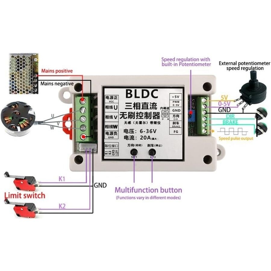
Interface
1. U V W 3-phase DC output connected to brushless motor
2. The 5V GND motherboard comes with 5V (external output current within 100MA)
3. VCC GND drive main power supply (external DC power supply)
4. FG speed pulse signal output (matching Tachometer is on sale in our store)
5. DIR forward and reverse control is effective at low levels (can be changed externally)
6. BRAKE brake control active brake with low level effect (externally replaceable)
7. 0-5V 1-4.2V PWM speed regulation control signal three input terminals (the board is equipped with a Potentiometer for speed regulation, and the 0-5V analog PWM duty ratio signal is also externally used for speed regulation bağlanabilir)