.png)


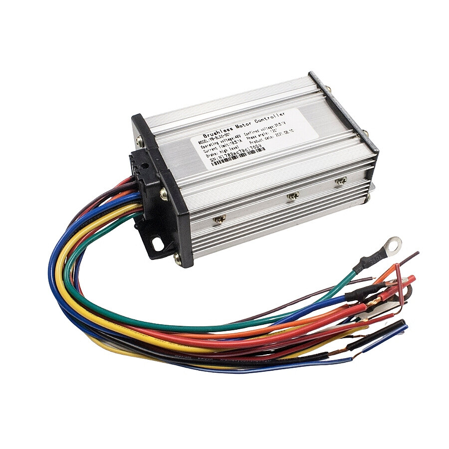
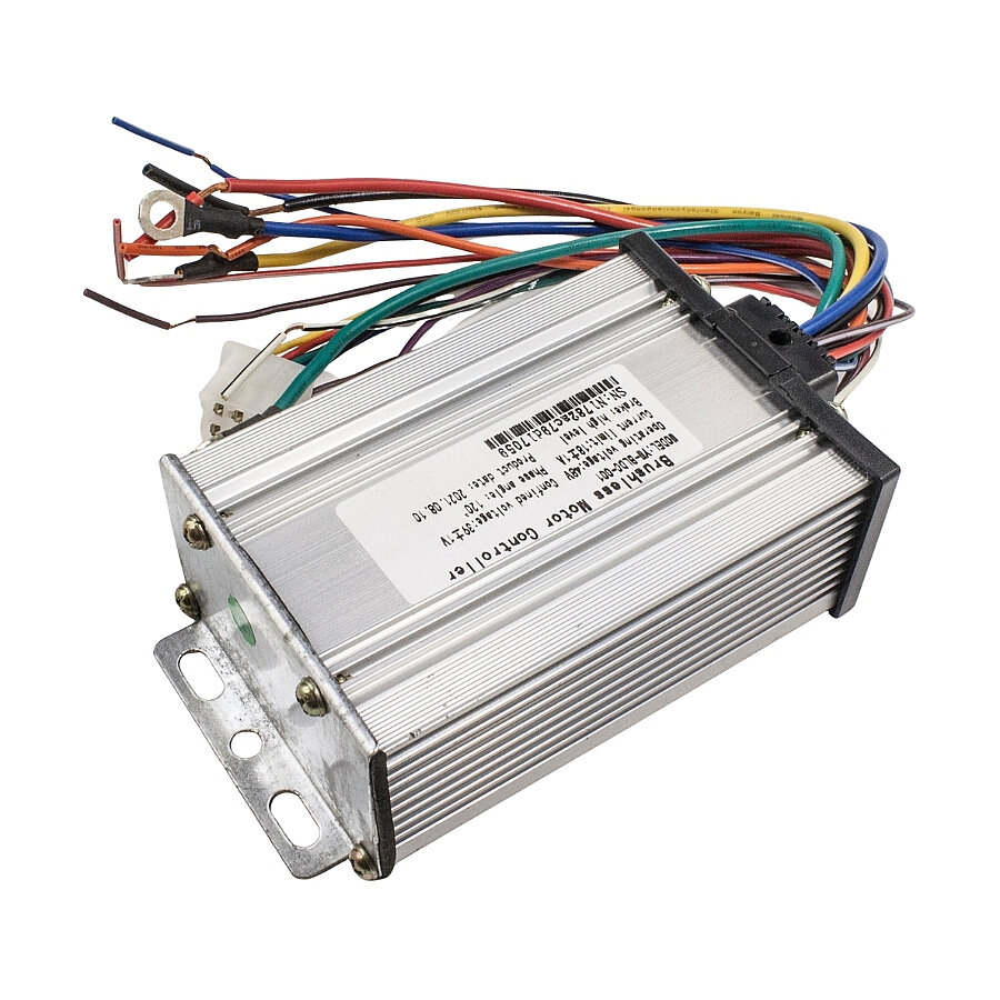
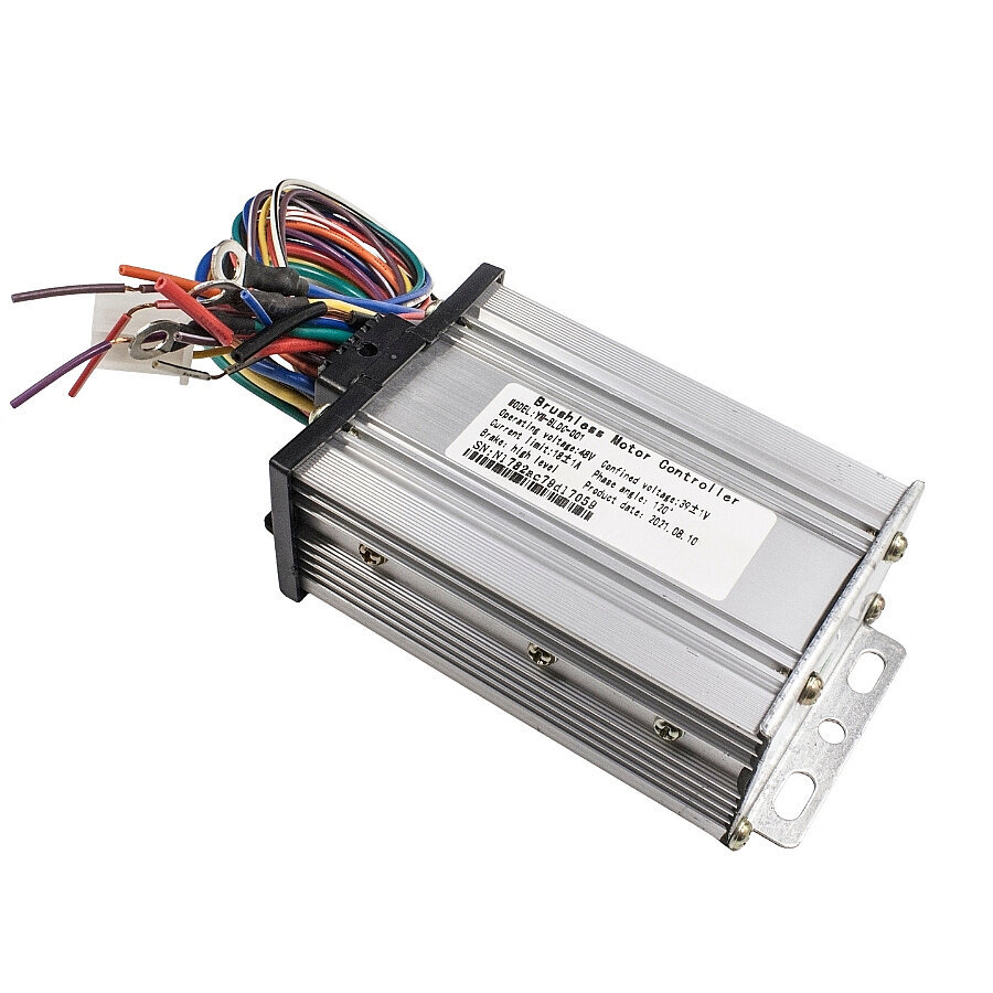
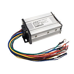
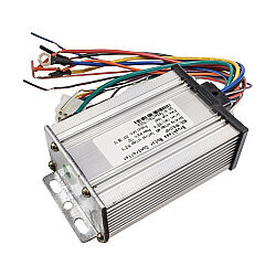
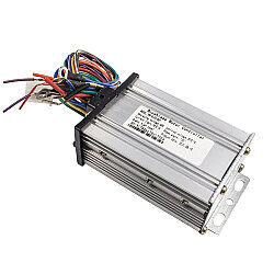
BLDC 48V 18A Brushless Motor Driver
BLDC 48V 18A Brushless Motor Controller
The BLDC 48V 18A Brushless Motor Controller is a compact and efficient control unit designed for brushless DC motors used in electric bicycles, scooters, and other light electric vehicle applications.
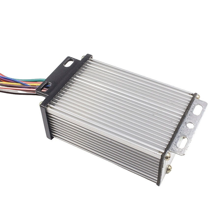
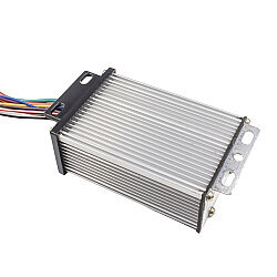
Featuring an aluminum alloy housing, the controller offers superior heat dissipation during operation. It is designed for systems with a 120° brushless motor phase angle.
Specifications
- Operating Voltage: 48VDC
- Rated Current: 18A
- Phase Angle: 120°
- Brake: High Level
- Output Cable Length: 20cm
- Case Dimensions: 105x68x40mm
Connections
Red (P+): Positive (+) terminal connection from the battery.
Black (P-): Negative (-) terminal connection from the battery.
2. Motor Phase Cables (Thick lines supplying power to the motor)
Blue (U): Motor Phase 1.
Yellow (V): Motor Phase 2.
Green (W): Motor Phase 3.
3. Hall Sensor Group (Motor position sensors)
Red (5V): Positive (+) supply for Hall sensors.
Black (GND) to connector: Negative (-) line for Hall sensors.
Blue (HA): Sensor A signal.
Green (HB): Sensor B signal.
Yellow (HC): Sensor C signal.
4. Display (Gauge) and Communication Connections
Orange (VCC): Ignition / Lock signal
Purple (TXD): Data transmission line from the controller to the display (Speed, error codes, etc.).
Red-White (4.3V) & Black (GND): Reference voltage, typically used to power the display or supply the throttle.
5. Functional Control Cables (Brake, Speed, Modes)
Black-White (SL): Low Brake line. When the brake is applied, this line connects to GND (negative); the controller cuts motor power and activates the brake light.
Blue-White (SD): Speed signal / Cruise Control or external throttle signal input.
Brown-White (K1): Typically the gear / speed level (3-Speed) switch or regenerative braking (motor braking) activation cable.