.png)


1
Comment
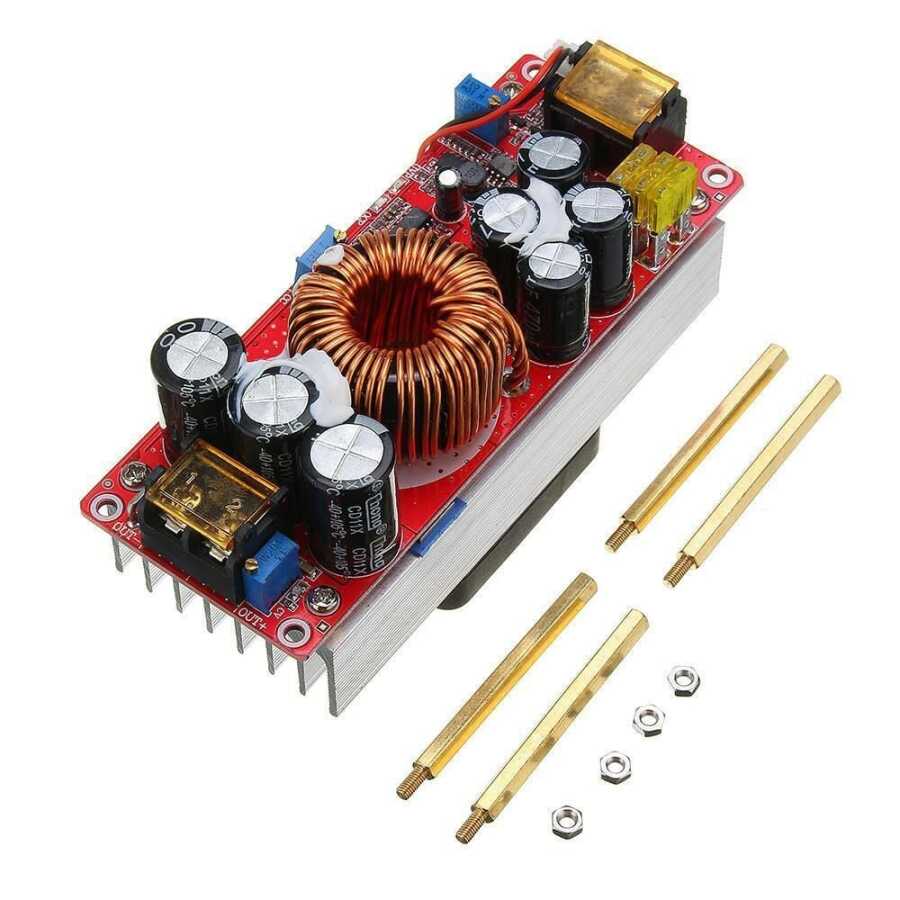
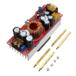
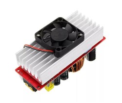
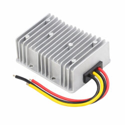
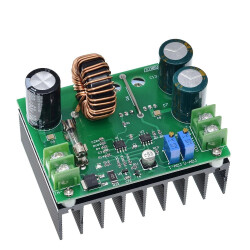
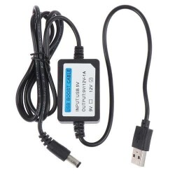
DC-DC 1500W 30A Voltage Amplifier Boost Module
1.175,00
TL
+
VAT
1.410,00
TL
Notify Me When It Arrives
1.175,00
TL
+
VAT
1.410,00
TL
Add to Favorite
RecommendCommentAlarm Price
DC-DC 1500W 30A Voltage Amplifier Boost Module
Maximum 30A input between 10-30V or With this booster module, which can input a maximum of 25A between 31-60V, you can get output in the range of 12-90V. It has a power resistance of up to 1500 watts. Suitable for use in industrial equipment, electronic devices, Communication Devices, Power Tools, LED lights, Fans, PDA or various digital products.
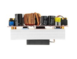
Technical Specifications
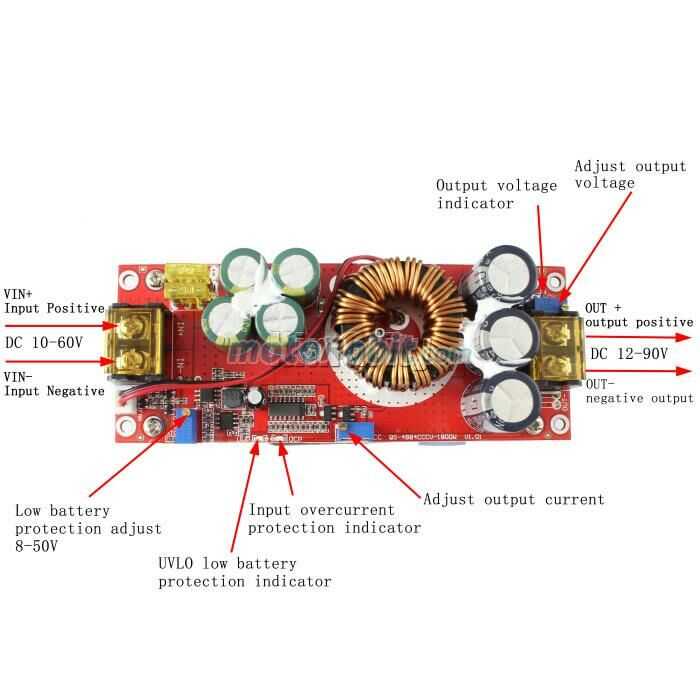
- Input Voltage: DC 10-60V
- Width: 37mm
- Input current : 10-30V input voltage, maximum current 30A / 31-60V input voltage, maximum current 25A
- Static operating current: 15mA
- Output voltage: 12-90V continuously adjustable
- Output current: 20A MAX (more than 15A, please strengthen heat dissipation)
- Constant current range: 0.8-20A (+/- 0.3A)
- Operating temperature: -40 ~ + 85 degrees
- Operating frequency: 150khz
- Input overcurrent protection: Yes
- Short circuit protection: Yes (input 30A fuse) Double short circuit protection, safer to use.
- Input reverse connection protection: Yes
- Wiring method: terminal block
- Module size: 130x52x70mm
Applications
- DIY power supply
- Electric bike charger
- As car power supply for your laptop, PDA or various digital products
- Solar panel boost regulator
When using the booster, you should pay attention to the following points:
- The output polarity cannot be reversed or short-circuited.
- Do not connect the batteries to the input. When using as a power supply, you should reduce the battery protection, otherwise it will damage the battery and the power supply.
- The input power supply voltage should be above 10V.
- When the power supply is used for the input supply, the input power and the output voltage of the input power source is the first source to be discharged. Then lift the load. (You must ensure that the switching power supply is working).
- When constant current mode is used to adjust the voltage, the constant voltage must be higher than the input voltage. Do not use the path of short circuit output current, the circuit structure of the booster module cannot be set to short circuit.
- If the input voltage fluctuation range is lower than the set output voltage, the output voltage is stable, to ensure that the input is lower than the output voltage.
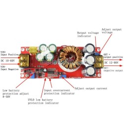
Voltage regulation
Straight to adjust the "V-ADJ" potentiometer to adjust the output terminal clockwise and counterclockwise to adjust Use a tip screwdriver. Because the output capacitor capacity is large, when the output voltage is adjusted from high voltage to a low voltage, the reaction slows down. The default output voltage is 19V. Since it is a voltage booster module, the input voltage must always be higher than the output voltage.
Current regulation
Adjust the "CC A-ADJ" potentiometer counterclockwise about 30 turns, set the output current to minimum, connect the load such as LED battery, and adjust the "CC A-ADJ" potentiometer clockwise to your desired current. To charge the battery, after the battery is discharged, connect it to the output and set the CC A-ADJ to the desired current. When charging, be sure to use the discharged battery to adjust the battery. The more the charge, the smaller the charging current. The default output is sent to ESC 3A. Do not use the short circuit output to adjust the current, the circuit structure of the booster module cannot be adjusted by short circuit.
Enter the low battery protection setting
Low battery protection prevents over-discharge of battery when input power is battery. The battery voltage is too low to damage the power module and battery. The input is low voltage protection when switching power supply.
SIMILAR PRODUCTS
258,50
TL
+
VAT
2.820,00
TL
+
VAT
1.076,30
TL
+
VAT
564,00
TL
+
VAT
681,50
TL
+
VAT

1.245,50
TL
+
VAT
30,55
TL
+
VAT
117,50
TL
+
VAT
258,50
TL
+
VAT