.png)


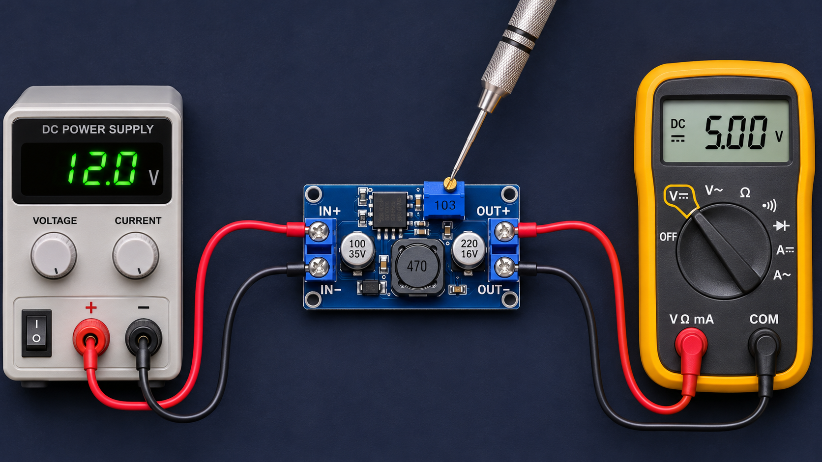
Adjustable buck converters are used to obtain 5 V from a 12 V adapter, reduce battery voltage to a level suitable for a microcontroller, or power several DC circuits from one supply. Connecting a device before adjusting the module, however, may expose it to a higher-than-expected voltage and cause permanent damage.
This beginner-friendly guide explains how to identify the input and output terminals, prepare a multimeter, and safely adjust a 12 V DC input to a 5.00 V DC output.
What Is a Buck Converter?
A buck converter is a switching regulator that changes a DC input voltage into a lower DC output voltage. For example, a 12 V input can be reduced to 9 V, 5 V, or 3.3 V. Because it switches energy instead of simply turning the excess voltage into heat, it can be more efficient than a linear regulator under suitable operating conditions.
| Module Marking | Meaning | Connection |
|---|---|---|
| IN+ | Positive input | Positive terminal of the DC power supply |
| IN− | Negative input | Negative terminal of the DC power supply |
| OUT+ | Positive output | Positive terminal of the load |
| OUT− | Negative output | Negative terminal of the load |
The small adjustable component on the module is called a trimmer potentiometer. Turning it with a precision screwdriver changes the output voltage. Some trimmers are multi-turn types and may require 10–20 turns before a visible change occurs.
Required Materials
- An adjustable DC-DC buck converter
- A low-voltage DC supply within the module’s input range
- A digital multimeter capable of measuring DC voltage
- Multimeter probes or insulated crocodile test leads
- A small screwdriver suitable for the trimmer
- Hookup wires and an optional fuse
Example product options:
- 2A Mini Adjustable Step-Down Regulator Board for compact, lower-power projects.
- 3A Mini Adjustable Step-Down Regulator Board for a wider input range and higher current requirements.
- XL4015 5A CC/CV Step-Down Module when adjustable current limiting is also required.
- DT-700D Digital Multimeter for DC voltage measurements and basic electronics testing.
- Multimeter probes and test leads
Browse the Motorobit step-down converter category for other voltage and power options.
Preparing the Multimeter
- Insert the black probe into COM.
- Insert the red probe into the V/Ω voltage socket.
- Set the selector to DC voltage, usually marked
V⎓orVDC. - On a manual-ranging meter, select a range above the expected value. The 20 V DC range is suitable for measuring 12 V.
Wiring the Converter and Multimeter
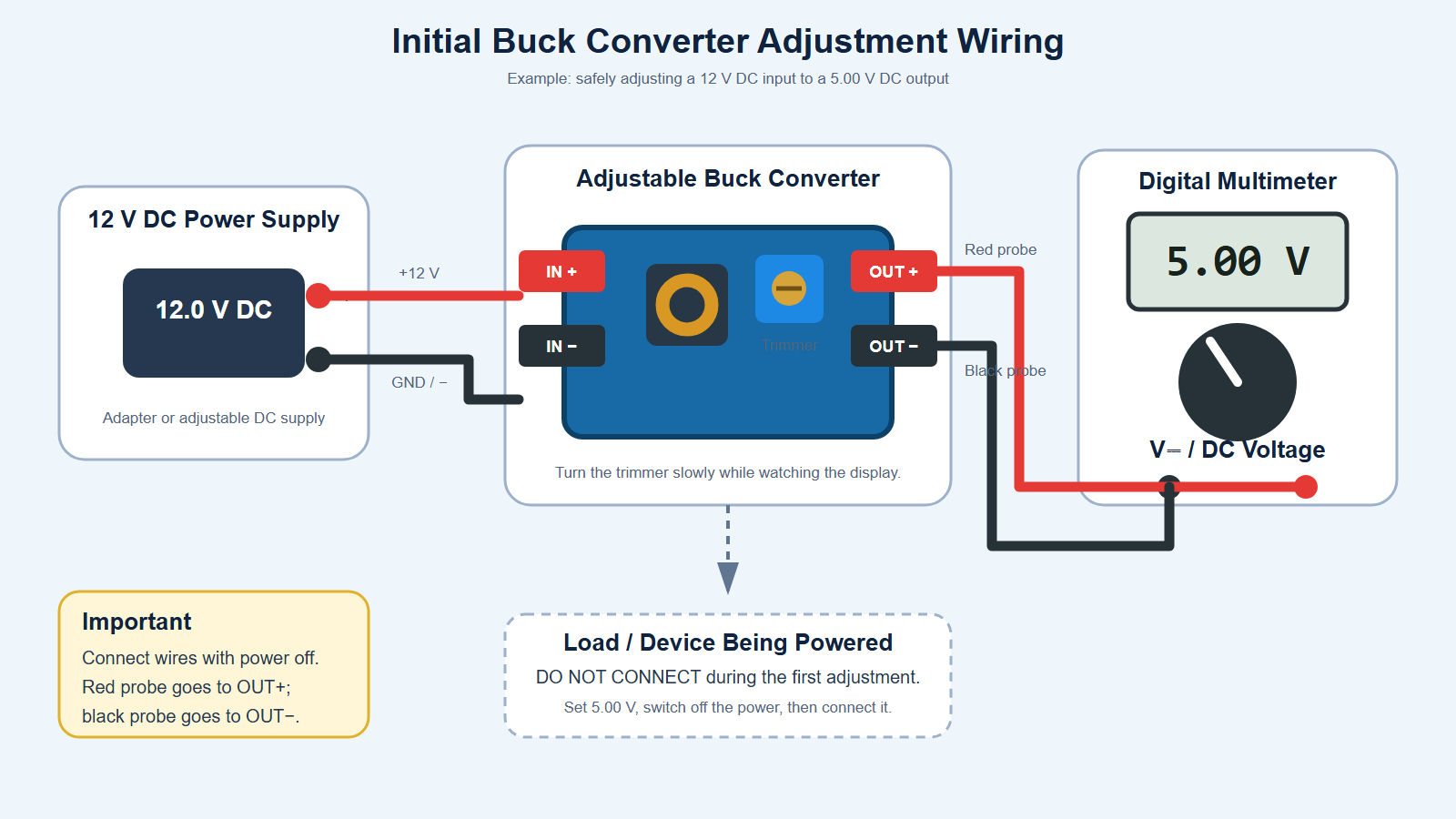
The multimeter is connected in parallel across OUT+ and OUT−. The load remains disconnected during the initial adjustment.
- Switch off or unplug the DC power supply.
- Connect the supply positive terminal to IN+.
- Connect the supply negative terminal to IN−.
- Place the red probe on OUT+ and the black probe on OUT−.
- Do not connect the device being powered yet.
- Confirm that no bare wires touch and that polarity is correct.
Adjusting 12 V Down to 5 V
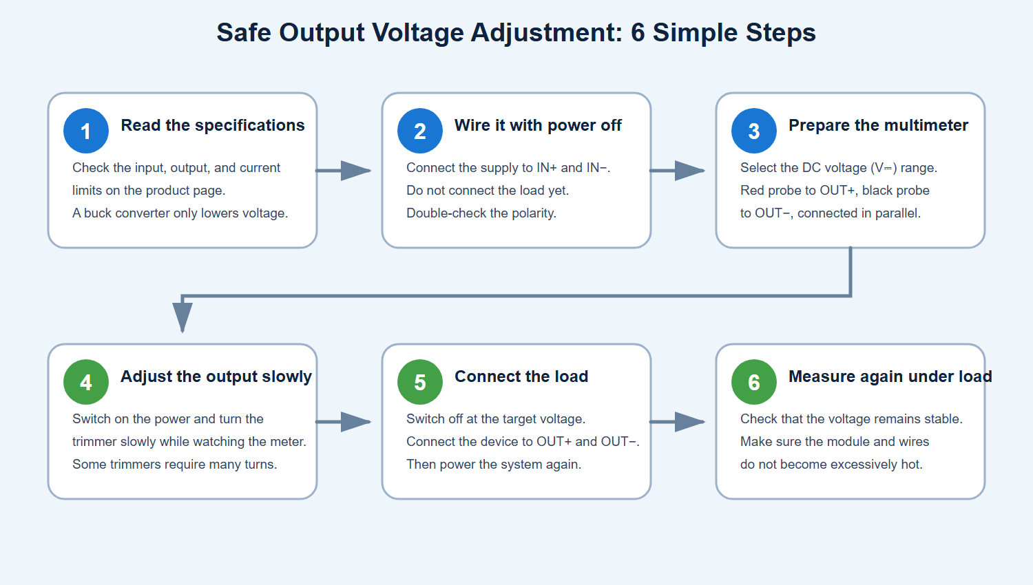
- Read the module specifications. Confirm that 12 V is within its input range and that it can produce a 5 V output.
- Complete the wiring with power off. Leave the load disconnected for the first adjustment.
- Set the meter to DC voltage. Confirm that the probes are on OUT+ and OUT−.
- Switch on the supply. Read the initial output voltage.
- Turn the trimmer slowly. Make small adjustments while watching the meter. If the voltage moves in the wrong direction, turn it the other way.
- Stop at 5.00 V. The required tolerance depends on the device being powered; exactly 5.000 V is not normally necessary.
- Switch off the power. Connect the load to OUT+ and OUT− with the correct polarity.
- Power the system again and measure under load. Confirm that the voltage remains acceptable and the converter does not overheat.
How Much Output Current Is Required?
A “3A” marking does not mean the module forces 3 amps into every connected device. The load draws the current it needs. The marking indicates the module’s upper capability under suitable conditions.
5 V × 1 A = 5 W
Input power is slightly higher than output power because the converter is not 100% efficient. At approximately 90% efficiency, a 5 W output requires about 5.56 W from the supply. With a 12 V input, this is roughly 0.46 A of input current.
Actual continuous current depends on the input-to-output voltage difference, cooling, airflow, PCB design, wiring, and ambient temperature. A published maximum should not automatically be treated as a safe continuous rating under every condition.
Single-Trimmer and CC/CV Modules
| Module Type | Adjustment | Typical Use |
|---|---|---|
| Single trimmer | Usually output voltage only | Microcontrollers, sensors, LED circuits, and fixed-voltage loads |
| Two-trimmer CC/CV | Voltage and current limit | Loads that require current limiting and properly designed charging applications |
On CC/CV modules, the voltage control is normally marked V-ADJ or CV, while the current control may be marked I-ADJ or CC. Current-limit adjustment requires a suitable test load and a procedure different from simple voltage measurement.
Why Measure Again Under Load?
An output that reads 5.00 V without a load may fall after the device is connected. Common causes include:
- Insufficient converter current capacity
- A power supply that cannot provide enough current
- Long, thin, or loose wires
- Input voltage that is too low
- Thermal protection caused by excessive heat
- High-resistance solder joints or terminals
Check both output voltage and converter temperature after connecting the load. Excessive heat may require a more powerful converter, heatsink, fan, or shorter and thicker wires.
Common Mistakes
| Mistake | Possible Result | Correct Approach |
|---|---|---|
| Reversing IN and OUT | The module may not work or may be damaged. | Read the PCB markings before applying power. |
| Reversing polarity | A module without reverse protection may fail. | Check positive and negative wires twice. |
| Making the first adjustment with the load connected | A high initial voltage may damage the load. | Adjust without a load, switch off, then connect it. |
| Setting the meter to AC voltage | The reading may be wrong or meaningless. | Select V⎓ / DC voltage. |
| Leaving the red probe in the 10A socket | A short circuit or blown fuse may result. | Use the V/Ω socket for voltage measurements. |
| Trying to raise voltage with a buck converter | The required output cannot be reached. | Use a boost or buck-boost converter. |
| Treating maximum current as continuous current | Overheating and unstable output may occur. | Leave a safety margin and test temperature under load. |
| Connecting directly to mains electricity | Fatal shock and fire hazards. | Use only the low-voltage DC input range specified for the module. |
Frequently Asked Questions
Why does the voltage not change when I turn the trimmer?
It may be a multi-turn trimmer and require several turns. Also check the input voltage, probe positions, and whether you are accidentally turning the current-limit trimmer on a CC/CV board.
Can I obtain exactly 12 V from a 12 V input?
Many buck converters require some difference between input and output for stable regulation. A buck-boost converter or a higher input voltage may be needed for a regulated 12 V output.
Can a 5 V output be connected to any development board?
No. The functions and limits of 5V, VIN, USB, and 3V3 pins differ between boards. Check the board documentation first. Applying 5 V to a 3.3 V-only pin may destroy the board.
Can the multimeter remain connected?
Yes, during a voltage test it is connected in parallel. Secure the probes so they cannot slip and create a short circuit; insulated crocodile clips are helpful.
Conclusion
The safest method is to read the specifications, wire the module with power off, adjust the output without a load, and measure again after the load is connected. Selecting DC voltage, keeping the red probe in the V/Ω socket, and checking polarity protects both the converter and the powered device.
Compare suitable options in the step-down converter category and browse digital multimeters for measurement equipment.